Introduction
Having always been interested in emulators and wanting to write my own, I decided to start with the very first computer I built at University, a Microtan 65.
Description
The main unit (uMachineMicrotan) sets the template format that the CHIP-8 and Space Invaders emulators use.
The preferences frame (uPrefsMicrotan) for the machine is created in this unit, and referenced by the Preferences form when it is created. This frame reads the settings used later; including the screen colours to use and the CPU frequency. The machine info is then defined, and the memory map, CPU, 6522 and screen are set up.
Thereafter the main loop in the Main Form repeatedly calls the RunForOneFrame procedure which executes the relevant number of instructions for one frame dependent on the machine frequency set. That procedure also checks for keyboard input, and refreshes the screen display.
Other procedures support saving and loading the machine state to a file.
Microtan 65 Commands
All commands are a single letter some with hexadecimal arguments. Refer to the original Microtan 65 user manual for details. A summary of commands includes:
-
M<address>
MEMORY EXAMINE / MODIFY; displays the content of a specified memory location <address> and allows it to be changed. The current content is displayed after the address. If you want to change it, type the new value. Pressing ENTER will store the new value (if there is one) and exit. Pressing Ctrl-ENTER (LF) stores the new value and opens up the next location. ESC stores the new value and opens up the previous location.
-
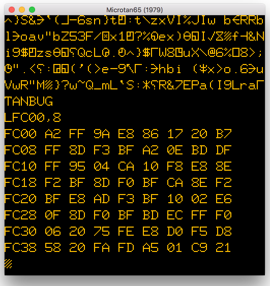
L<address>,<number of lines>
LIST MEMORY; displays the contents of a section of memory starting at <address> and lists <number of lines> of eight bytes each. If zero lines are requested then 256 lines will be listed.
-
G<address>
GO; start execution of a program with first instruction at memory location <address>. The program will run until a BRK instruction is encountered or the machine is reset.
-
R
REGISTER DISPLAY / MODIFY; Memory locations $15 to $1B hold the CPU pseudo registers. The CPU registers are loaded from these locations when a program is executed with the G command, and are stored there when a BRK instruction is executed, prior to the system returning to TANBUG. The R command is a short version of a M0015 command to display and modify the CPU registers.
$15 = PC low byte, $16 = PC high byte, $17 = PSW, $18 = SP, $19 = X, $1A = Y, $1B = A -
S
SINGLE INSTRUCTION MODE; when enabled, the program will execute one instruction at a time, with the CPU registers displayed after each instruction.
-
N
NORMAL MODE; disables single instruction mode. Automatically set when CPU is reset
-
P
PROCEED; executes the next instruction in single instruction mode. If the P command is followed with a number, that number of instructions will be executed.
-
B<address>,<breakpoint number>
SET / CLEAR BREAKPOINT; where <address> is the address of an instruction opcode where the breakpoint is to be set, and <number> is 0-7 to specify one of eight breakpoints. When the G command is executed the program runs normally until a breakpoint is reached and execution then stops. To clear a breakpoint set its address to zero, or B by itself will clear all breakpoints. [Caution: read the manual for details of how this command works to avoid potential corruption of the program]
-
C<source start address>,<source end address>,<destination start address>
COPY MEMORY; copy one block of memory (defined by source start to source end) to another location (beginning at destination start).
References / Resources
- Microtan 65
- Microtan 65 User Manual, includes TANBUG V2 [PDF]
- TANEX User Manual [PDF]
- XBUG User Manual [PDF]
- Microtan BASIC User Manual [PDF]
- Tanbug Source Code Listing
- Programming the 6502
- MCS6500 Family Programming Manual (1976) [PDF]
- 6502 Assembly Language Programming – Leventhal (1979) [PDF]
- Programming the 6502 – Zaks (4th Edition 1983) [PDF]
- Advanced 6502 Programming – Zaks (1982) [PDF]

