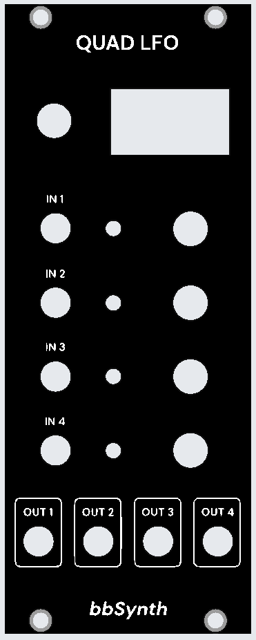
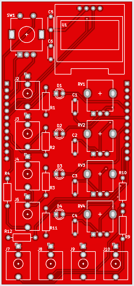
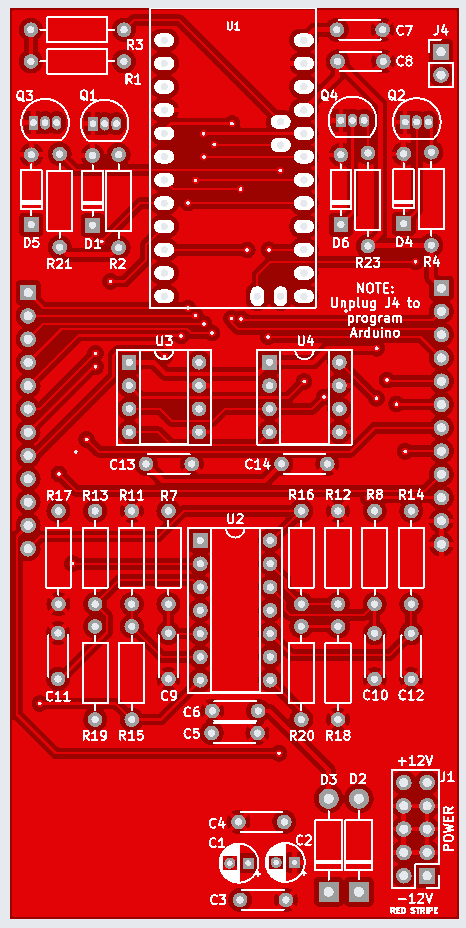
Every synthesiser uses at least one LFO (Low Frequency Oscillator) to provide modulation signals to other modules.
Having found various DIY options using Arduino I decided to go down that route. I wanted some sort of wavetable generation and multiple LFO channels in one module, and this made using PWM difficult given there was only one 16-bit timer in the Arduino Pro Mini I was using. So I went with external DACs and decided on a four-channel LFO based on Rich Heslip’s code (GitHub).
Panel / PCB manufacture
The schematic and PCB/panel were designed using the open source EDA (Electronic Design Automation) software KiCAD, a fabulous piece of software.
I decided to follow a lot of other people to get PCBs made and a front panel too, using the services of JLCPCB. Five sets of all three items cost just £20 to get made up, including international postage! The front panel is black with white silkscreen and I had the PCBs done in a rather cool red.
Lessons Learned
- Inadvertently omitted LED series resistor and had to bodge by bending LED leg and adding resistor. Updated schematic / PCB to include resistors
- Having done initial testing via USB-to-TTL adapter to observe serial output, applied +/-12V with control panel detached and no TL074/MCP4822 and tested voltages ok. Arduino was in place, LED lit for a few seconds then went out; the onboard regulator had died… apparently happens with Chinese clones. Added external 7805 and capacitors on little board. Thought of 78L05 but 100mA might be insufficient for Arduino (~20mA), OLED (~20mA) and LEDs. Amended schematic and PCB, with jumper option to allow external rack +5V via 16-way power connector, or +5V from newly added onboard regulator
- NOTE: RS PRO K78L05 switching regulator (£3.55) is a pin compatible replacement for 7805 with 500mA capacity. Much higher efficiency / lower losses
- On test two of the sync inputs did not work properly. The 2N3904 transistor leads are only spaced 1mm and solder bridges rendered them ineffective. Took some effort to fix. Revised PCB with wider footprint giving 2.54mm spacing
- Can use internal MCU pull-ups for sync inputs; removed 10k resistors and amended code to use internal pull-ups in MCU
- Outputs give 0-5V with current resistor settings; Rin=10k, Rf=2k2 (gain 1.22 with MCP4822 max 4.096 output). Suggest change Rf to 15K for 0-10V output (gain 2.5). Can attenuate via OLED / rotary encoder
- Revised layout of PCB to accommodate above changes
References / Resources
- Files on Titan:
/Archive_Jekyll/files/electronics/synthesiser/…02-quad-lfobuild, links too… the software and hardware files are in the GitHub folderMySynth Quad LFO
- USB-to-TTL adapter 5V cables: Blue(DTR)-Orange-Yellow-White-Black-N/C


